In 1959 I wrote a piece published in the UCL Engineering Society Journal 1958-59. It was called "A Car for the Future". I graduated with a B.Sc. in electrical engineering and worked for the BBC for 6 years then emigrated to the USA. I worked in aerospace and then started a company in medical electronics, then in it's infancy. I retired but after a few years of house remodeling I found an interesting job where electric motors were being used to replace pneumatic ones in surgical tools. I learned how to design electric motors using FEA and was successful in starting a motor division in the company. Finally retired again and began to think about my original interest in electric cars. This started with the need for a powered perambulator because we lived on the top of a hill and my wife found coming back from shopping with a baby too much. I built a simple chain driven one speed drive for the carriage. It used a 24 volt ex aircraft motor and trolley bus batteries that together weighed more than the groceries and baby!.


THE CAR PROJECT
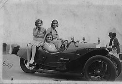
The idea for a car that I could build started when I was a very young man about 60 years ago. I found a photo of my mother sitting on the back of a 1930s three wheeled Morgan. It was now time, I thought, to build a 3 wheeled electric car that had both the old fashioned appeal of the Morgan plus the application of the latest technology to operate the car. I needed a frame or chassis to start and I picked out a Spitfire sports car for the chassis and front suspension.
The wheels on the Spitfire were too small , I wanted the larger diameter of the 1930s style. This meant changing the assembly and I found new ones that also had the correct stud mounts for new wheels. The old ones were removed and very carefully I welded on the new.


This is a model of what I first thought of for the car. No compound curves, just like the Morgan!
Here is the mess after stripping most of the Spitfire away. I wanted only the bare chassis and front suspension.


This is with the new wheel checked after mounting
Original wheel and tire
Now I had a viable front end and needed the rear. I chose the Harley Davidson motor cycle as a choice because it has a separate gearbox and also the suspension is neatly hidden underneath.
Now the basic car frame was completed but where to put the foot controls and steering wheel?

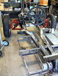
Above: The left over Spitfire chassis plus the added on Harley Davidson rear. The rear chassis was then cut away once the geometry was confirmed. It would have been nice to have a laser alignment tool here!

Almost everything in position. The overall length needed to be increased to allow for seating and foot controls. you can just see a motor and the transmission, a 5 speed motorbike sequential gearbox with hydraulic clutch.
Adding motor mounts and battery racks took much time and adding a frame of steel square tube by welding to the existing chassis came next ....


Here are 4 of the eight packs, each pack held cells to make up 20 Ahr 50 volt LiPO4 or about 1 Kwhr capacity. The 8 packs are connected in series to make a nominal 400 volt power bus. The packs were distributed below the seat and on each side as low as possible. They are in racks to allow for easy removal.
The battery racks in place , one set on each side.
This is the four motor assembly, they were connected mechanically via toothed belts with one belt on each end. One of the belts also wrapped around the clutch input. Electrically they could be connected in series or parallel via contactors. These DC brushed motors were eventually discarded as the mechanical structure proved unstable. A single brushless Pm motor was installed in the current version waiting for my custom motor to be added.
Batteries... this has proven to be the most difficult part of the project. I chose a 400 volt 20 Ahr capacity to keep wiring sizes down. Using off the shelf batteries proved impossible , all sources were Chinese and I had no way to control quality. The first set failed before the car was ready to drive, the cells were poorly welded together and their BMS ( battery maintenance system ) was not well designed. The next batteries were individual cells that I assembled into 7 packs that still fitted into the existing racks. These lasted about 2 years and then failed bybeing unable to store more than 50% of capacity. Finally using nearly 2000 individual 18560 cells with different chemistry the new packs store almost 16 kWhrs . Finally after trying to use chipsets from two leading IC manufacturers I chose to buy a complete BMS module. Each cell is connected to the BMS so the wiring for this is intensive but essential.


Dead cells from the first battery packs....
BMS from first packs.
Second set, prismatic LiPO4 cells , 14 cells in each pack. Note all cells have their own monitoring leadwires.
This is the current pack, each pack of 7 contains 18650 cells wired in series -parallel, to give a nominal 50 volts per pack, each pack has two monitoring thermistors. 2000 cells is a lot of connections! ( ala TESLA)
The bodywork


The bodywork mock up was made using stryrene sheet until it looked OK. Then the complete body was made using ABS sheet 3mm thick the outer side being smooth. ABS was chosen because of its great properties, it is heat bendable being a thermoplastic, it is weldable using solvents such as MEK or acetone, it is very strong and stable. It is easy to cut using woodworking tools .


Here are some of the ABS pieces, rear license plate holder, armrests, front section. The mudguards ( "fenders" in USA ) were made from PVC pipe using a 120 degree section.
Side panel with armrest in place, eventually all side panels and rear section were welded together.
The Control System
I decided that the main control would be using an Arduino , this would have sufficient power to handle most of the tasks . It had to interface with a display , the BMS under CANBUS, and also I wanted a bluetooth connection to a smart phone app. The Arduino used is the Mega 2650 that has over 50 I/O ports plus some A to D input ports.
A bluetooth shield and a Sparkfun serial I/O complete the control. Their are two programs one for the Arduino and an APK for the Android smartphone. The smart phone is physically mounted on the center of the steering wheel and runs a custom app.
The motor controller is a commercial servo motor controller capable of 50 amp max and 100 amps for 10 seconds at a max voltage of 400. This is adequate for the current motor as it is capable of about 15 HP at 5000 RPM. The system may be run with or without the smartphone as I was concerned about the reliability of the bluetooth connection. The only control that is exclusively under the smartphone control are the hazard lights. All else is duplicated by the in car controls. g ) .
The battery is monitored via a BMS that communicates to the Arduino via CANBUS, this gives each cell voltage that is displayed on the smartphone. It also provides battery current . The battery current and miles traveled are used to compute the range and this feeds to an analog old fashioned fuel gage mounted on the dash. There are also a speedometer and tachometer on the dash that use via some D/A conversion done in the Arduino accurate readings and look OK for the old fashioned styling.
The gear box is a 5 speed sequential box and as the usual method for changing gears is via a foot pedal I decided to use pneumatic cylinder driven from a small air tank that is kept to pressure by a tiny 12 volt compressor. the shifting is done using a floor mounted joystick that has up and down shifting in the 12 and 6 O'clock and fwd and reverse in the 3 and 9 O'clock positions. The usual car functions like lights and horn are controlled via the Arduino and the outputs are fed to solid state relays ( using a mosfet for power switching


Final info


After completing the body I had it painted professionally and also found an upholsterer who works on old cars who made a very comfortable bench seat.

Future plans
The current motor is not adequate, top speed is about 45 mph and hill climbing is poor. I have designed and built a motor that has about 4 times the output power and weighs the same. With the new motor and a new controller the car will be capable of over 70 mph and hill climbing will be fun. The three wheeled configuration and wide front combined with a very low c.g allows for excellent road handling. As battery technology improves range that is currently about 50 miles will be extended to 100, adequate for a local fun car.
If you are looking for a motor that has special qualities this is the place where you can get the motor you need . We specialize in motors with unusual or very special requirements, size, power , efficiency, voltage, torque, etc... you tell us what you want and we will get back in a few days with a clear response.