The Concept...
This a brushless permanent magnet motor, three phase Y connected.
The target was to see how lightweight and compact I could design and build a motor that could be used in EVs or aircraft. The configuration chosen was bi-axial separate phase windings, this was a unusual arrangement but one that looked to have promise. Efficiency becomes critical due to the thermal system. Unless the efficiency is very high the temperatures of the motor components become unacceptable. Losses occur in the ferromagnetic parts, the windings and also some in windage.
Here is how I approached the design:

Ferromagnetics
The materials commonly used are silicon steel or cobalt alloys; the steel laminations have reasonable losses but as the frequency of induction increases the losses become significant, cobalt alloys alloy for almost twice the saturation flux but have high losses unless made in very thin laminations and are very expensive. I looked at transformers and found that C Core transformers were available made using extremely thin material called Metglas that has only 20% of the loses of silicon steel, and intended for use at high frequencies and high saturation flux densities. It was available in almost any shape that can be wound on a form but I selected a standard C- Core to enable the project to proceed quickly.
One of the C-Cores . i had problems with the manufacturer keeping my dimensions especially the overall length. Not importnat for a transformer but critical for my design.
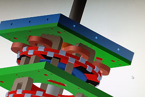
The design was drawn using 3D graphics and all the parts drawn and specified for manufacture. This shows the cores in gray, the windings in reddish brown , the magnets in red, the other parts were structural and not magnetic although the blue end plate was aluminum that proved to need changing due to eddy current losses in it.
This is a FEA result of a 2D model that
was used to determine the basic field
strengths that would be found in the design. The length and dimensions of the C-Cores was only changed once due to an increase in the rotor magnetics that increased the field high enough to make the losses in the cores too high. The accuracy of the FEA was close enough to the result of that it proved invaluable. A 3D analysis FEA would have yielded slightly better results, but the 2D results were within 10% of the actual.

Conductor losses, windings
The configuration was for each phase to have two identical facing windings. By separating the phases there would be minimal copper that was not used to supply torque, no end turns meant no losses. The windings were on the each group of 6 cores, the winding being in series. This looked very simple but became the most difficult part of the project. Many winding methods were tried without success, what was needed was to be able to pack as much copper as possible in to the slots. Flat strip was tried but eddy current losses were excessive, then multiparallel wire that proved impossible to place in sufficient density, finally flattened wire wound in a parallel configuration proved successful.
This method could be easily duplicated in production with minimal tooling.
Magnetics


On the left is a pair of the
coils placed on a core, these are in the final configuration of 14 parallel flat wires with high temp insulation. Each coil is wound as a pair and connected in series around the 6 cores as shown. The insulation was Kapton but the cores required a special treatment to prevent their extremely sharp corners from cutting into the windings. No bobbins were used to increase the space for copper.
On the right is a one of many false starts in the winding methods.

Getting the winding in the right direction proved troublesome!

The choice was simple Neodymium Iron Boron magnets are so much superior to anything that all I needed to do was to decide on the shape and grade. I chose a 40SH grade that is good for motors because it can withstand high temperatures but still has phenomenal magnetic strength . To retain the magnets that are the rotors and spin at motor speed retention was a challenge , the solution was to enclose the magnets in stainless steel laser welded together. Tests upto 10,000 RPM show excellent stability.

This is one of the three rotors, the method to attach them to the shaft and to be able to orient them correctly at 20 degree from each other was resolved using a wedge clamping system. This view is before laser welding. An earlier attempt at retaining the magnets using steel tabs failed at 7,000 RPM and subsequent calculation of the forces verified this to be an unacceptable retention method.
Mechanicals
The design was completed using Solid Works that also allowed for production of drawings for manufacture. The drawings were sent to selected Chinese manufacturers who would accpet a very limited production, the quality and speed of the service was outstanding.
A shaft diameter of 5/8" was chosen but 3/4" would have been better as it's stiffness would make for less vibrations caused by the magnetic pull.

The unpacking and checking of the parts. The accuracy and quality was exactly as specified. Some materials like the epoxy glass , in black, had exceptionally difficult CNC machining. Some parts were in stainless steel and others in aluminum alloy.
Assembly
This was difficult at first because of the enormous forces of the magnetic rotors. After considerable effort a method that was simple and reproducible was developed. The shaft was inserted into a bearing in one of the end plates, then a alignment disk was attached to the shaft via a wedging clamp and it was then locked in rotational and axial directions. then each phase was added and aligned by 4 axial rods and the shaft. As each phase was completed the alignment system was rotated 20 degrees and locked , corresponding to the correct position based on the rotor magnets. Spacing between the rotors and the C-Cores was achieved by plastic strips that were removed later. A fairly large air gap was possible due to the very high magnetic field. On review the magnets could have been thinner and then the gaps would have been smaller. This didn't affect performance but it would have resulted in lower production costs.


Top left is the alignment system that was removed once all phases had been installed. The top right shows the work area with three rotors ready for installation. the lower left shows one phase just before the rotor was applied. On the right is a trial assembly without magnets,


This shows one of the phases with a rotor. The magnet with the yellow tape was used to identify polarity of the rotor magnets. The metallic tabs were used to connect the coils, although the use of flat strips added losses it was convenient. In the next iteration the interconnections will be by flattened wire to reduce eddy current losses.
Testing
First rotor was spun at speeds that the motor is to be used to be sure of the integrity of the rotors. Then It was spun to determine the waveform and to verify the correct Hall sensing connections to be made to the motor controller. The top waveforms are the phase voltages and the lower the Hall sensing signals. The waveform is essentially sinusoidal so a sine wave drive would be an ideal match but we used a trapezoidal drive system as this was available. Commercially available sine wave drive controllers in the voltage and power levels we need are not available although used in current EV's they use proprietary software that makes them not usable for us.


Test results
The motor and hall sensing circuit ( mounted at one end ) was connected to an A-M-C servo motor controller limited to 50 amps and 400 volts. We ran the motor at various speeds to determine losses and also a motor constant. The resistance of the windings was measured using a constant current method since the value is too low for a standard VOM.
We also ran the motor and monitored the temperatures of the components using a non-contact IR thermometer.
Based on this we arrived at the following specifications for the motor.
Motor specifications:
weight: 13.6kgs.
dimensions: 150 x 150 x 350 mm.
max speed: 10,000 RPM
output power : at 10,000 RPM, 50 HP at 96% efficiency continuous, 100 HP for 10 seconds all with forced air cooling.
maximum torque : 400 amps x .6 = 240nm. (180 ft-lbs)
motor constants: Kv ( volts/1000 RPM ) = 60 volts/1000 rpm. = 0.6 volts/radian/second.
now kt = kv in SI units.... Kt ( nm/amp )=0.6 nm/A
motor resistance Rm = 0.22 ohms.
Typical operation conditions. Ignoring drop due to motor resistance Rm, 300 volts applied the speed will be 5000 RPM , if the load requires 100 amps then the torque generated will be 100 x .6nm = 60nm.
Total power input 300 x 100 =30 Kwatts. Copper losses = 10,000 x .22 =
2200 watts. Efficiency ( ignoring other losses that are less than 5% )
= 93%. at 400 volts in and same current power input = 40 Kw almost same losses so efficiency =95%.